
Updated: 17th February 2017
It’s 13th November 2017 and I’ve just started to design my liquid cooled RF amplifier for 23cm Amateur Television (ATV).
WHY LIQUID COOLED?
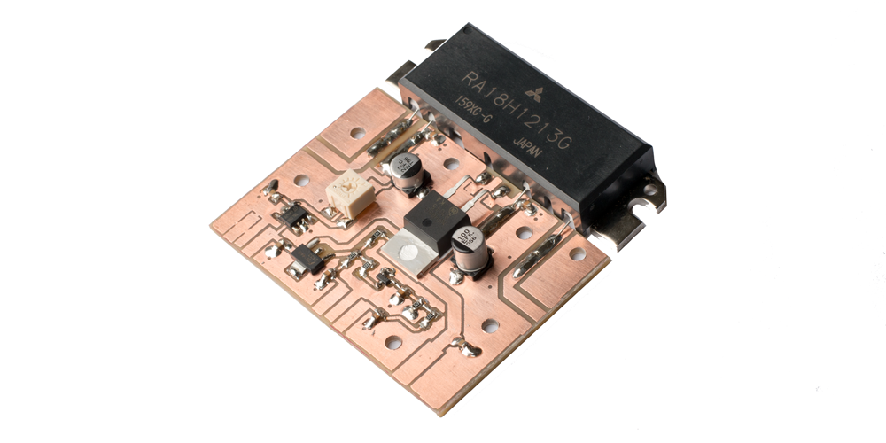
A few months ago I built an 18W RF amplifier (below) using a Mitsubishi RA18H1213G LDMOS module.
This amplifier was designed by Steve Drury, callsign G6ALU and full details can be found here www.radio-kits.co.uk
View the technical data sheet for the Mitsubishi RA18H1213G here.

For cooling I used an Akasa AK-865 Compact AMD Cooler. This comprised of heatsink and 80mm diameter fan. Running at 18W the module generated a lot of heat so the fan needed to be run all the time and I found it to be noisy and irritating after a while.
I started thinking about how I could use a liquid cooling system for my amplifier. Designed well and with the radiator and cooling fans located outside the shack I concluded I could build not only a near silent running system but also a work of art.
SURPLUS ALLOY CASINGS
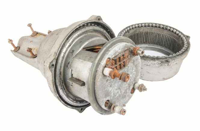
I intended buying a piece of alloy block and using my milling machine to machine a casing for my amplifier. However, whilst attending the September 2017 National Hamfest in Newark, Nottinghamshire, I came across a guy selling some surplus combiners for £3 each. I decided that with some modification that one would be ideal to house my amplifier and other projects, so bought three.

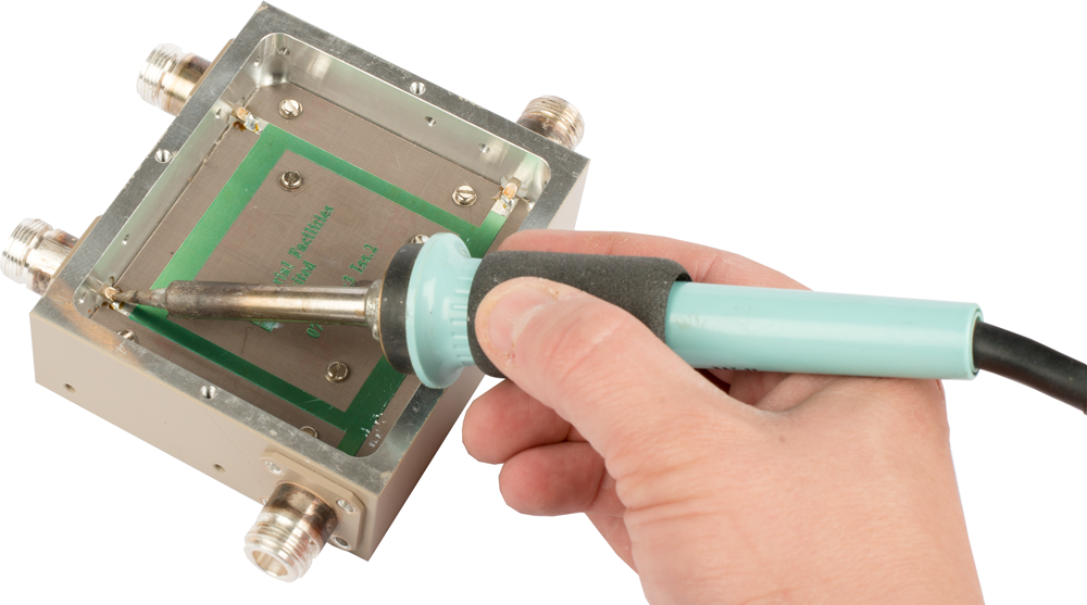
INSIDE THE SURPLUS CASING
Removing the lid from the casing revealed the combiner Printed Circuit Board (PCB). Using a soldering iron I desoldered the N-type connectors before removing PCB from the casing.
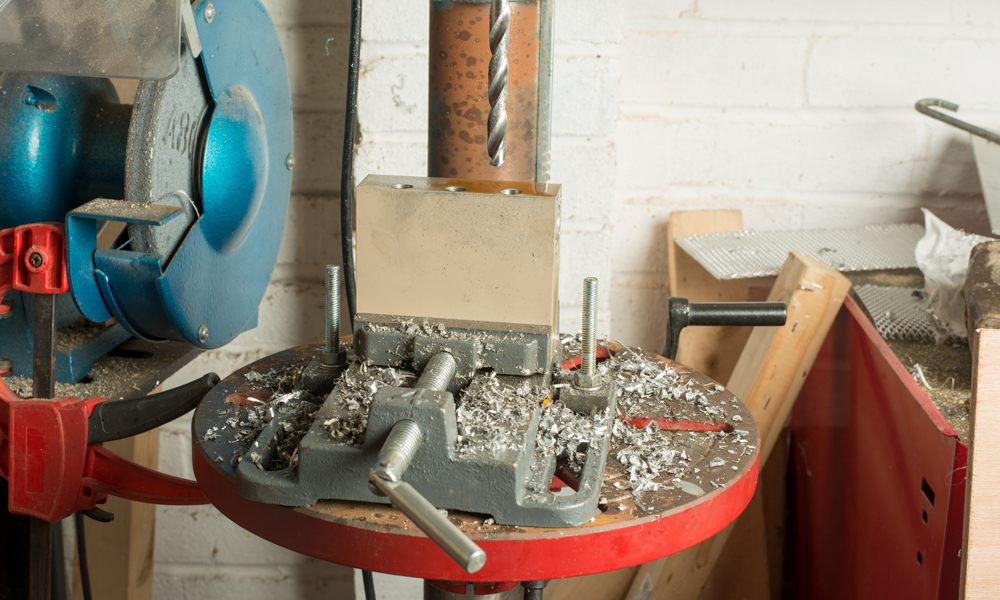
DRILLING HOLES FOR COOLANT
For the coolant pipe I am using 10mm diameter microbore copper pipe. I drilled three 10mm holes all the way through the casing.
I had planned on using my milling machine with collet and machine vice as this is much more accurate than a standard drill chuck. Unfortunately after drilling down to a depth of 15mm on the first hole, one of my milling machine gears broke. I considered putting the project on hold but after testing accuracy of my drill press I decided to use that instead. I was also forced to use my drill press vice because my machine vice didn’t fit.
Using a fast cutting speed I first drilled holes of 6mm diameter drill bit before finishing with a 10mm bit. I used an ample amount of cutting fluid to lubricate and cool the bit.
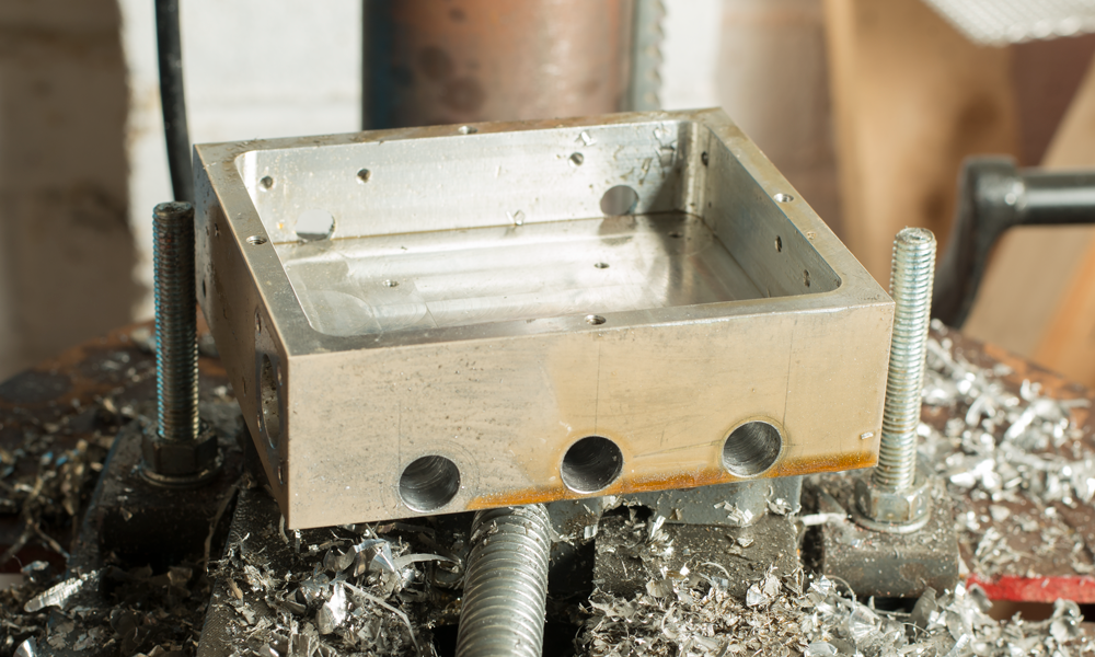
Below is an image showing the top of the alloy casing with the three holes drilled.
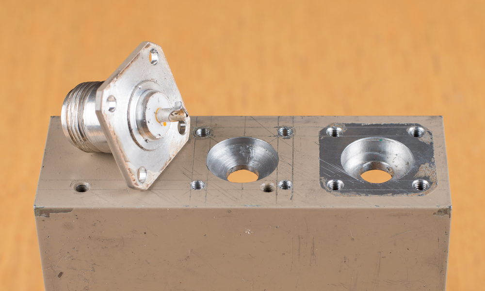
DRILLING RECESS AND TAPPING HOLES FOR N-TYPE PANEL MOUNT CONNECTORS
To avoid having to make significant modifications to PCB layout I decided to relocate the N-Type panel mount connectors so they were centered on each side of the casing. Again using a rule, vernier calipers, scribes and punch, I marked the position for the centre hole and recess, and also the fastener holes.
Using my pillar drill I first drilled the centre hole using a 7mm bit before drilling the recess with a 15mm bit.
For the fasteners I used a 2.5mm drill bit and then tapped the holes using a 3mm x 0.5mm tap.
PCB MODIFICATION
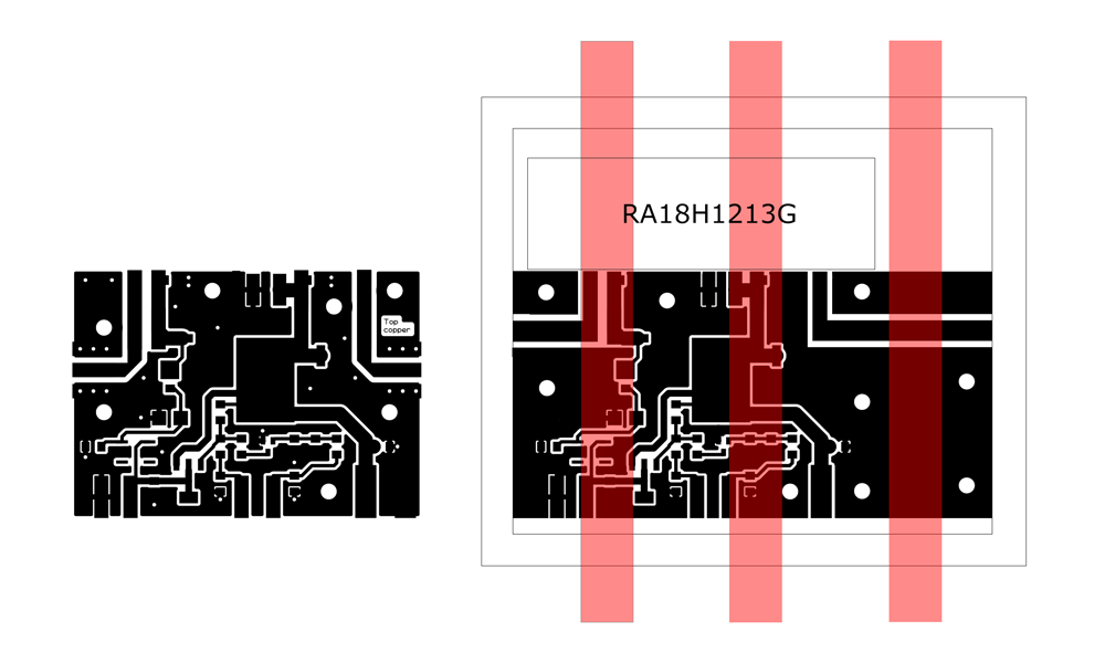
Below is the original PCB design I used to build my first RF amplifier (left) and the one I have modified using Adobe Photoshop CC to fit the new casing (right). The main changes were to make the PCB wider, increase the width of the track for the centre conductor of the N-Type connectors and change the position of the holes for the fasteners so they don’t go through the copper tubing (red).
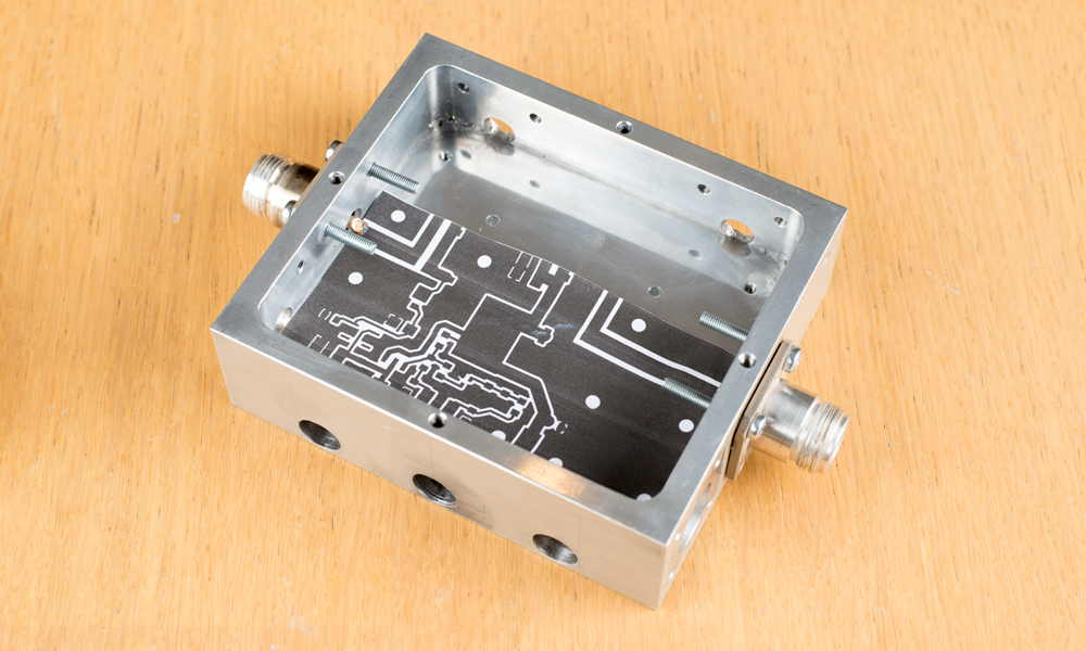
 TESTING PCB FIT
After modifying the PCB I printed it on paper and tested the fit with N-Type panel connectors fitted.
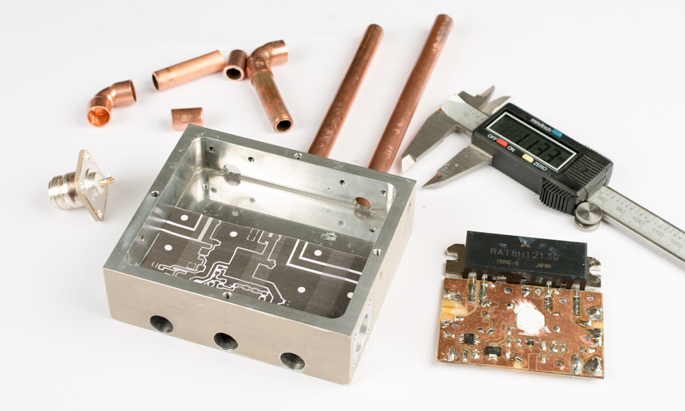
MEASURING COPPER TUBING
I measured all of the pieces of copper tubing, cut them using a pipe cutter and soldered them together using flux and solder.
ETCHING THE PCB
I printed the PCB on to Press-n-Peel film using a high quality laser printer and used the process in the video below to etch the PCB.
After etching the PCB looked that in the photo below. I used a pillar drill with 3.5mm drill bit to drill the holes for the mounting bolts.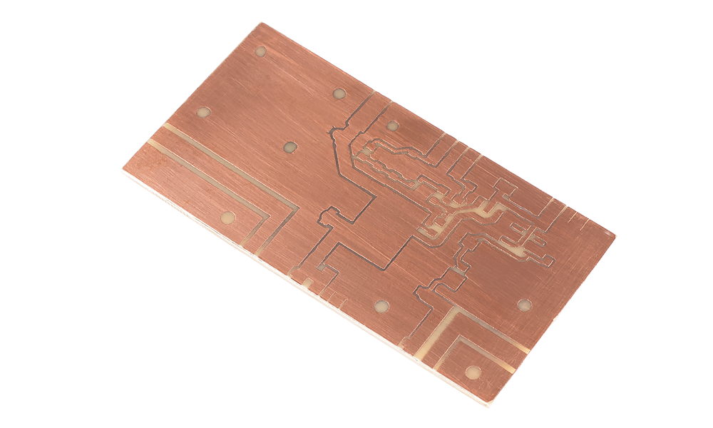
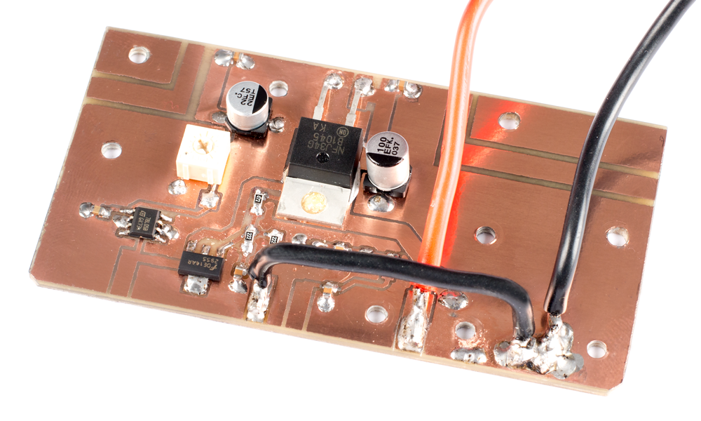
SOLDERING THE COMPONENTS ONTO THE PCB
After giving the PCB a final clean with PCB cleaner I soldered the components onto the board. I didn’t solder the Mitsubishi RA18H123G module because I wanted to test the RF module bias pad measured 0-5V by adjusting the variable resistor first as advised by Steve Drury, G6ALU, in his construction document.
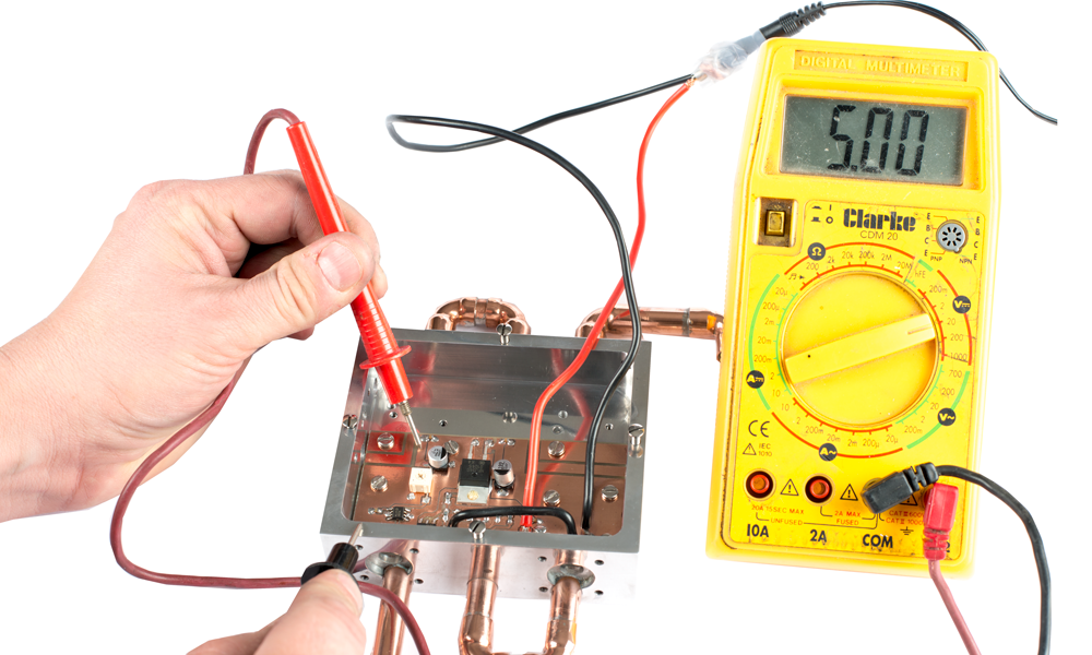
TESTING RF MODULE BIAS PAD SWING 0-5V
With the PCB fastened to the alloy casing I used a low current 12V power supply to test the voltage on the RF module bias pad. Changing the resistance of the variable resistor resulted in a voltage swing of 0-5V.
POLISHING THE CASING AND TUBING
I removed the PCB from the casing and set work to polishing the alloy casing and copper tubing. I used wet and dry 600-3000 grit, Autosol metal polish and a polish cloth.

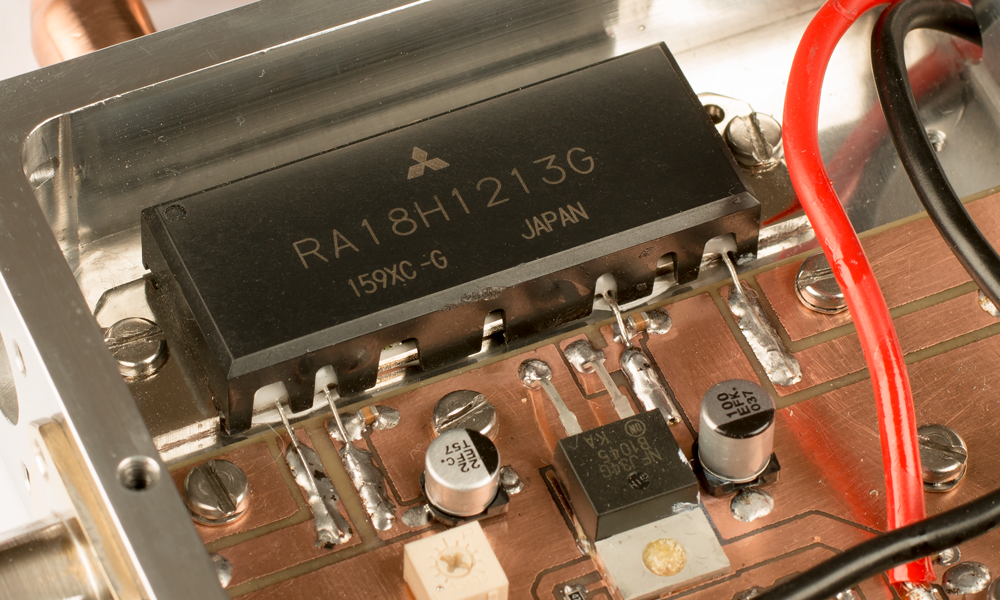
SOLDERING THE MITSUBISHI RA18H1213G MODULE
Ensuring the PCB was clean I soldered in the RA18H1213G module.
FITTING N-TYPE PANEL SOCKETS
I secured the N-TYPE panel sockets in place using M3 bolts and soldered the centre conductors to the PCB.

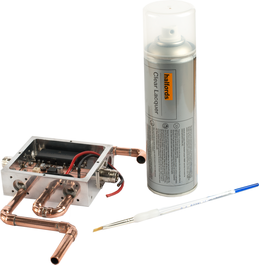
LAQUERING THE PCB
Using a small rectangular brush I lacquered the PCB using Halfords clear lacquer. I have used this lacquer a number of times before and much prefer this to PCB lacquers I have in my workshop. It takes approximately 24 hours to dry and has a really nice finish.
NEXT STEPS
To be continued…
Why not take a look at my YouTube channel here or Twitter posts here.
You can also register for my website here.
Thanks
73 de M0NWK
![]()


4 comments
Those modules get HOT!! I blew mine up. 🙁 do everything you can to conduct heat away as fast as you can!
73 de KM3G
Tyler
Google search: basementlabs881 that will show the amp module i replaced mine with.
Thanks for the details on your alternative amp module Tyler.
Thanks for your feedback Tyler. A few months ago I built the same amplifier. I used an Akasa AK-865 Compact AMD Cooler, machining the surface flat before fitting. Running at a constant 18W it got very hot but the fan and heat sink did a good job of cooling it. Just noisy. This liquid cooled design should take heat away fast and keep at a good temperature. It will have a control unit and 4 x temperature monitoring points. More on this soon.