Using a capacitor to block DC voltage in the Humax Foxsat satellite receiver for 23cm Amateur Television (ATV)
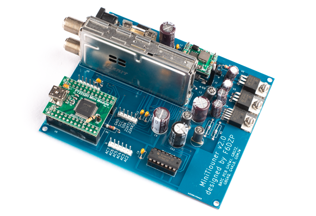
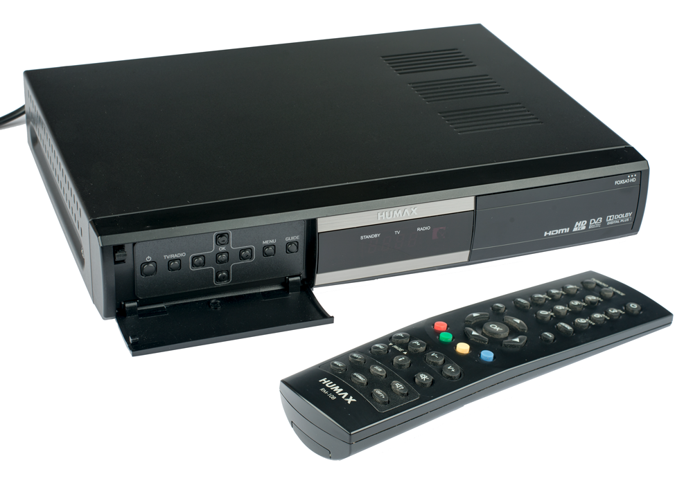
To receive 1.3 GHz (23cm) digital Amateur Television (ATV) transmissions from my local repeater GB3VL, I am using a Humax Foxsat HD/GB (click here for user manual) digital satellite receiver.
As standard, the receiver outputs 13/18V DC 500mA via the F-type coaxial connector on the rear of the unit. This voltage is delivered to the LNB that is connected to the satellite dish via the coaxial cable.
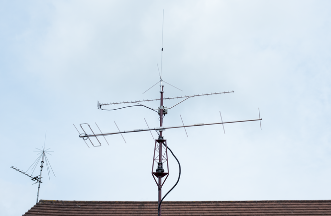
The satellite receiver is able to receive frequencies in the range of 950MHz to 2150MHz so there is no requirement to use an LNB or dish. Instead, I am using a WIMO SHF-2344, 44 element yagi antenna. The WIMO uses a folded dipole as the driven element.
Why block the DC output voltage?
It is important to block the DC output voltage before connecting the antenna to avoid causing an electrical short.
Some receivers have an option within the software to turn the power off but this is not possible in my Humax receiver.
Seeking advice from G7JFI
Wondering how best to proceed, I contacted Terry, G7JFI, who is a member of the Lincoln Repeater Group. Terry told me about a simple modification to block the DC voltage using a capacitor. A capacitor is used because it will block the DC voltage but will let RF pass. He also gave me a 10pf 1KV ceramic capacitor for the modification.
Capacitor modification
Tools required:
- Wire cutters
- Solder
- Solder sucker
- Soldering iron
- Multimeter
Parts required:
- 10pf 1KV ceramic capacitor
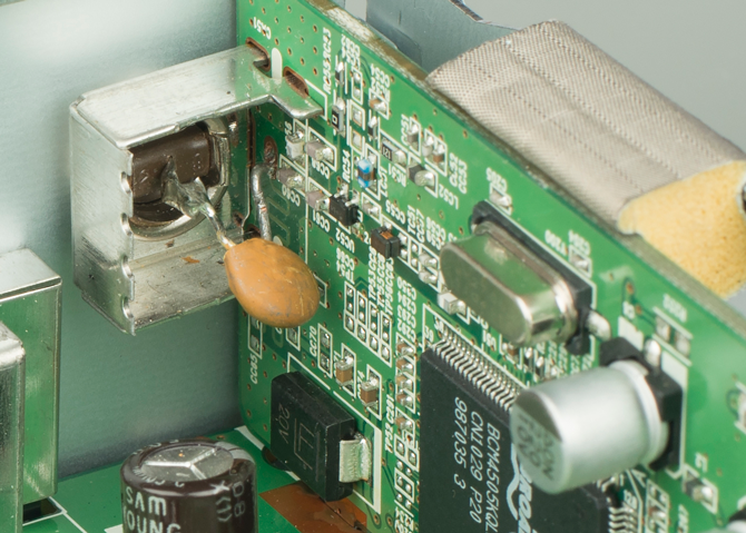
Here are the steps of the modification:
- Remove the PCB from the chassis.
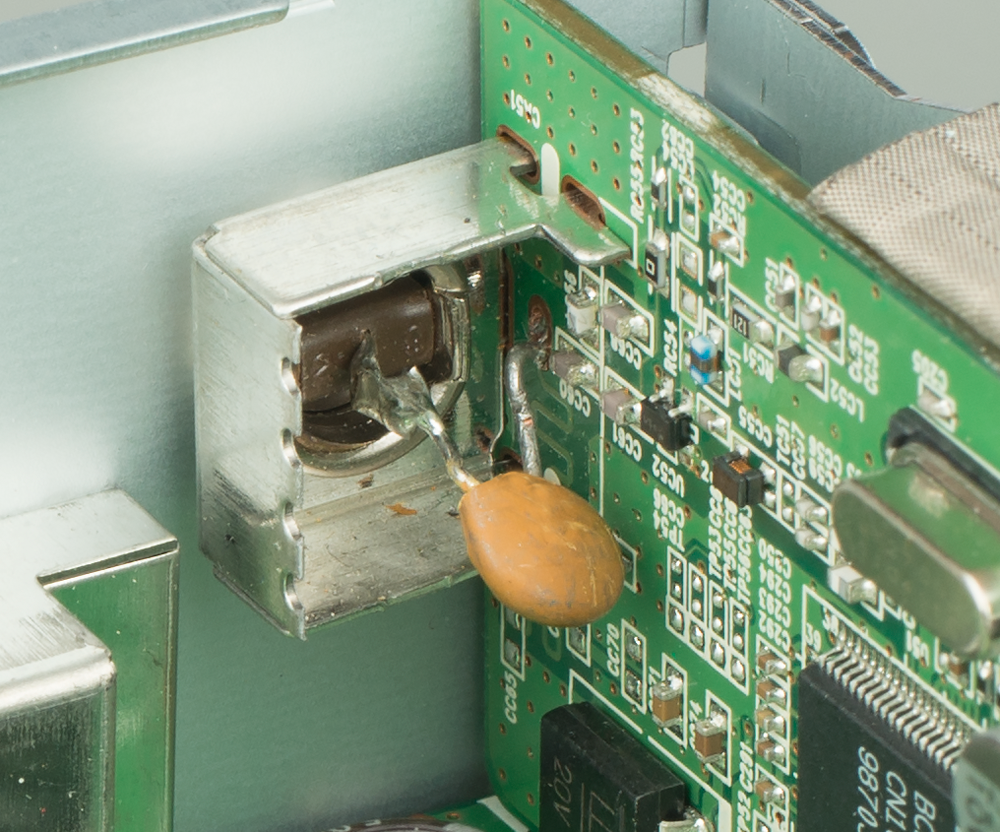
- Remove the piece of metal that covers the rear of the F-type socket to gain access to the centre conductor.
- Cut the centre conductor using a wire cutter, leaving approximately 8mm of centre conductor on the rear of the F-type socket.
- Desoldered the centre conductor from the PCB.
- Solder one leg of the capacitor to the circuit board and the other to the centre conductor on the F-type connector.
Testing the capacitor modification
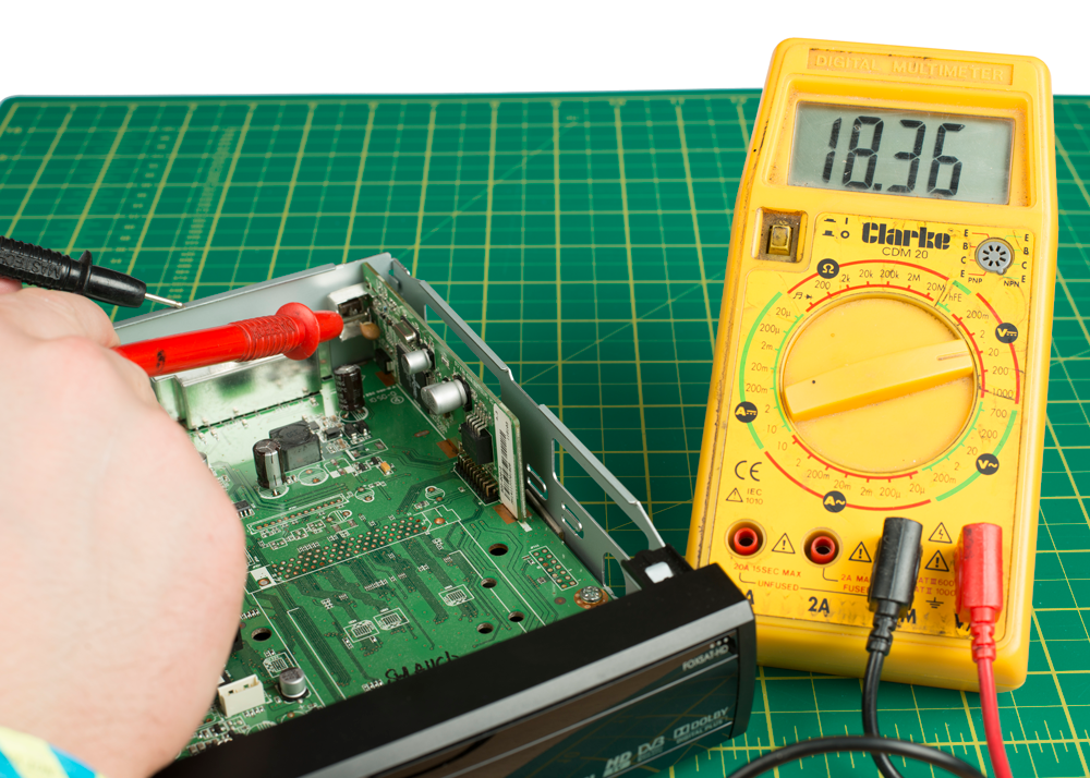
Using a multimeter set to 20VDC, I placed the negative probe on the chassis and the positive probe on the leg of the capacitor soldered to the PCB. This showed a voltage of 18.36V. This test proves the PCB is still outputting voltage.
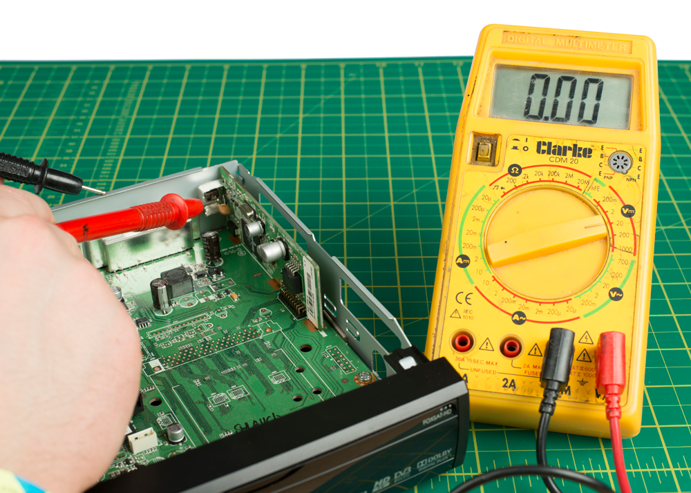
I then placed the positive probe on the leg of the capacitor soldered to the F-type connector. This showed a voltage of 0V, which means the modification has worked and the capacitor is blocking the voltage output from the PCB.
Conclusion
This is a simple, low cost solution that works and requires only a few basic tools to complete.
Good luck with your modification.
Why not take a look at my YouTube channel here or Twitter posts here.
You can also register for my website here.
Thanks
73 de M0NWK
![]()