
MiniTiouner hardware was designed by Jean-Pierre F6DZP and is a DVB-S/S2 USB receiver that works with MiniTioune software. It covers 143MHz to 2450MHz and was designed for use by Amateur Television (ATV) operators.
Like other amateur radio operators I want to use the MiniTiouner and software to receive transmissions from the Es’hail 2 QO-100 geostationary satellite.
I built my MiniTiouner (phase 1) in January 2019 but due to work commitments have just got round to using it.
Click on the continue button to see more.
PHASE 1
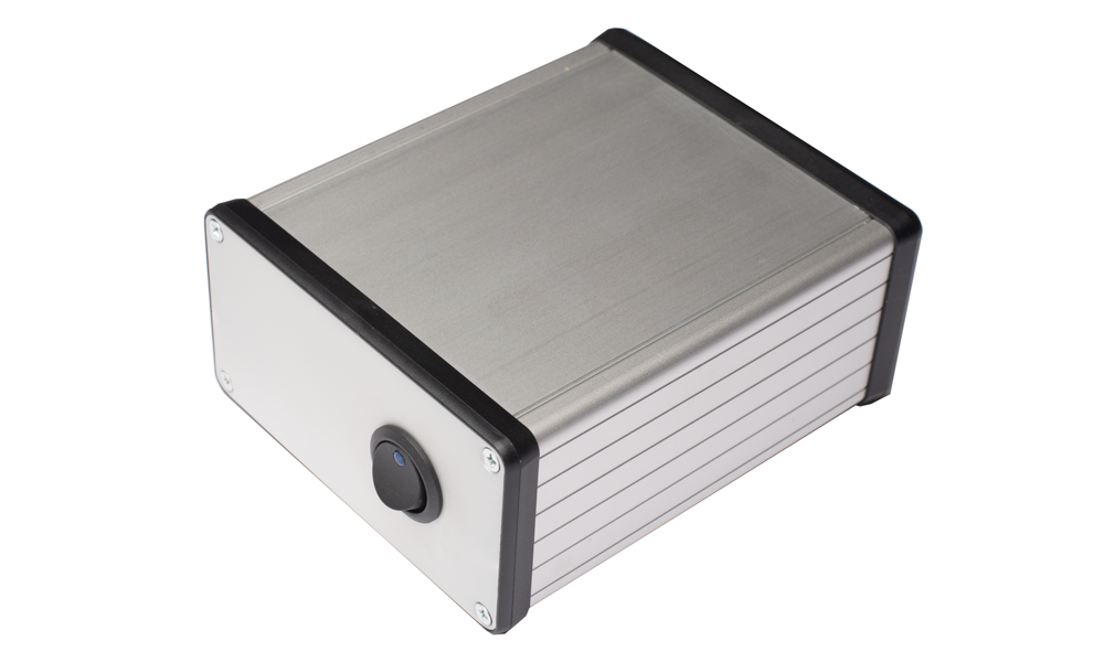
Phase one is to build the standard MiniTiouner, albeit with the addition of a power switch on the front panel and DC socket on the rear panel. The MiniTiouner can output 12V from each of the two F-type plugs which can be used to power an LNB. 12V is fine to receive vertically polarised signals but will require an 18V power supply and Bias T to make the LNB switch to horizontal and protect the receiver.
In future phases I will be adding a switch to turn on / off LNB power and also switch between 12V and 18V.
I will also be fitting an OLED to the front panel of the MiniTiouner so frequency and RF level etc. can be displayed.
ES’HAIL – OSCAR-100
Find out all about Es’hail-2 here
MINITIOUNER PROJECT
Want to build a MiniTiouner? Find all the info here
MY PARTS LIST
The purchased the MiniTiouner USB interface module, Serit FTS-434LU NIM tuner module, MiniTiouner PCB and MCP1826 1V regulator from the BATC website. Total cost of these parts was £56 including delivery.
All the components and case I purchased from Digi-Key apart from the MP1584 3A DC-DC buck Voltage regulator (£3.30 from eBay), switch (£1 from Newark Auto Jumble), DC panel socket (£1.50 from eBay), USB cable (free) and M3 x 10mm bolts, nuts and locking washers (£0.10 from Newark Auto Jumble). Total cost of Digi-Key parts was £40.94.
I made a jumper for J2 using a Dupont jumper wire. So taking into consideration a bit of solder, the overall project cost is just over £100.
TIPS
Here are a few of my tips for this project:
- Read the build instructions carefully before you start Click here for more information.
- Use Blu Tack to hold components in place but be careful not to put it directly where will be soldering as it melts.
- Get some PCB and flux cleaner. Use it to clean the PCB and remove any Blu Tac residue.
- Test the MP1584 DC-DC regulator and set before fitting (and re-check once fitted). I fitted one only to find it was faulty and spent 30 mins de-soldering it.
- Get some soldering braid for de-soldering and tidying up.
- Before bending the legs on the Voltage regulators temporarily fix them in place using M3 nut and bolt. Using a fine marker pen mark where the legs will need to be bent, remove the Voltage regulator to bend the legs and once bent refit using nuts, bolts and washers. Finally solder the pins to the board. This ensures a perfect fit.
- Test the fit of the MiniTiouner PCB board if you are using Hammond case suggested by BATC.
- If using a centre punch to mark the aluminium for drilling or cutting use a flat surface to place the panel onto and use only light force on the punch. The aluminium of the Hammond cases is very soft and easy to distort if too much force is used.
- Use a jewellers set of files to cut small holes like the one for the USB socket on the FTDI module.
BUILDING THE MINITIOUNER
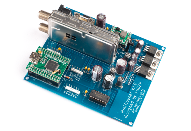
I built the MiniTiouner using the instructions on the BATC Wikipedia site. Click here for more information. Apart from the points below I soldered components in no particular order.
The key points of the build are:
- Do not fit jumper 2, Serit or FTDI (FT2232H) modules before set you have set the DC-DC regulator to output between 3.7V and 4V. I set mine to 3.75V.
- Once the DC-DC regulator is set to have output between 3.7V and 4V solder it onto the board.
- Test Voltage at jumper 2 again to esnure it hasn’t changed since you set it.
- If Voltage okay then fit jumper 2 but do not fit Serit or FTDI modules. Measure the Voltage of each ferrite RFC. They must measure (within specified tolerance) L1 = 3.3 V, L2 = 1.1 V, L3 = 3.3 V).
- Assuming ferrite RFC measurements are good, fit the Serit and FTDI (FT2232H) modules.
- A resistor between 5.6k and 12K must be fitted on the FTDI (FT2232H) module to use MiniTiouner version 0.8 software.
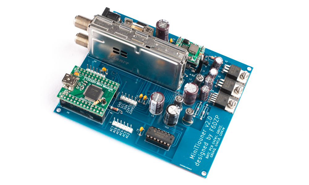
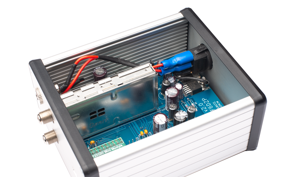
Another photo of the completed build but this time from the other side.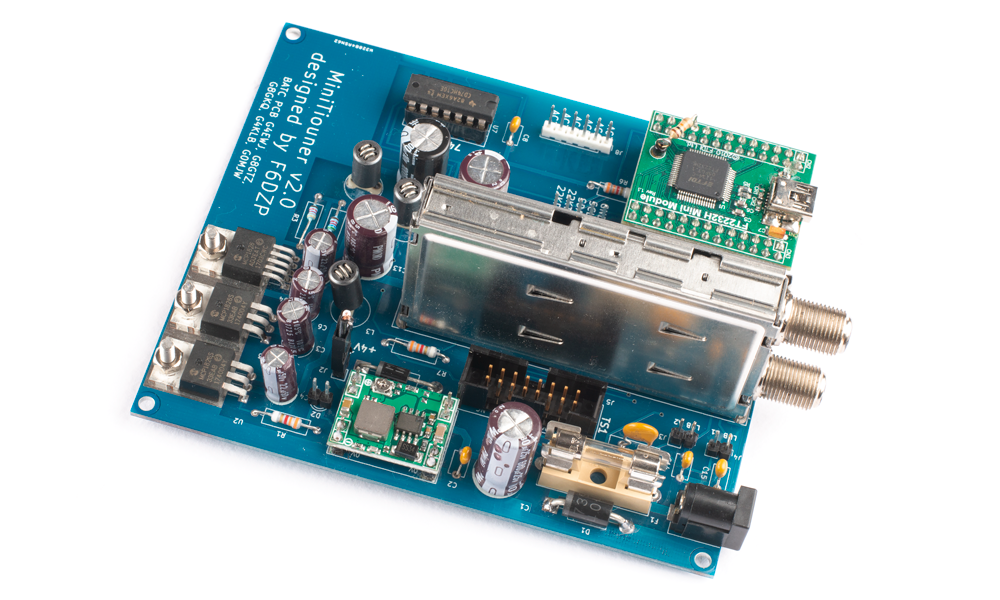
I opted to use the Hammond natural aluminium case (Digi-Key part number HMD974-ND / Hammond part number 1455N1201). The MiniTiouner PCB fitted exactly into the enclosure.
The build instruction document contains dimensions for the holes in the end panel. Unfortunately I have found too often that mistakes or variation in build quality affects where the holes should be drilled, filed and cut so I marked these positions myself.
I used a black drywipe pen to mark each end of the components.

I then stuck a piece of paper on the panel and gently slid the PCB into the case so the component marked the paper. I did this for the two F-type connectors and USB socket on the FTDI module.
I removed the panel and marked the centre of each hole using a centre punch before drilling, cutting and filing.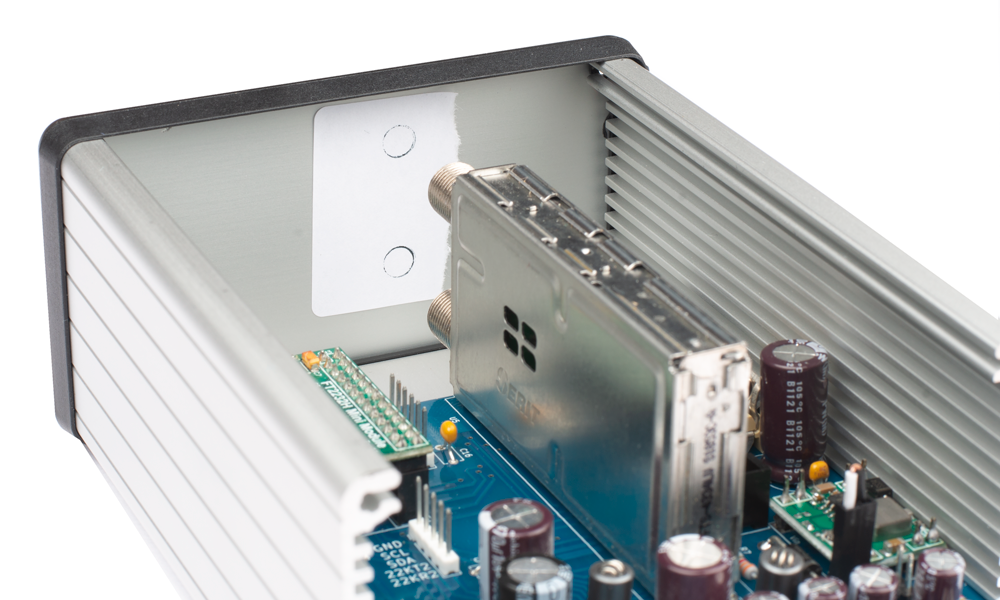
Rather than use the power supply switch to control power going to the MiniTiouner, I decided I wanted a power switch and indicator on the front panel of the MiniTiouner. Firstly I de-soldered the PCB mounted DC socket and fitted a panel mounted one on the rear panel. 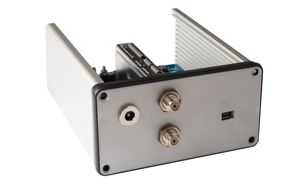
I then drilled the front panel and fitted a power switch with built in LED indicator. 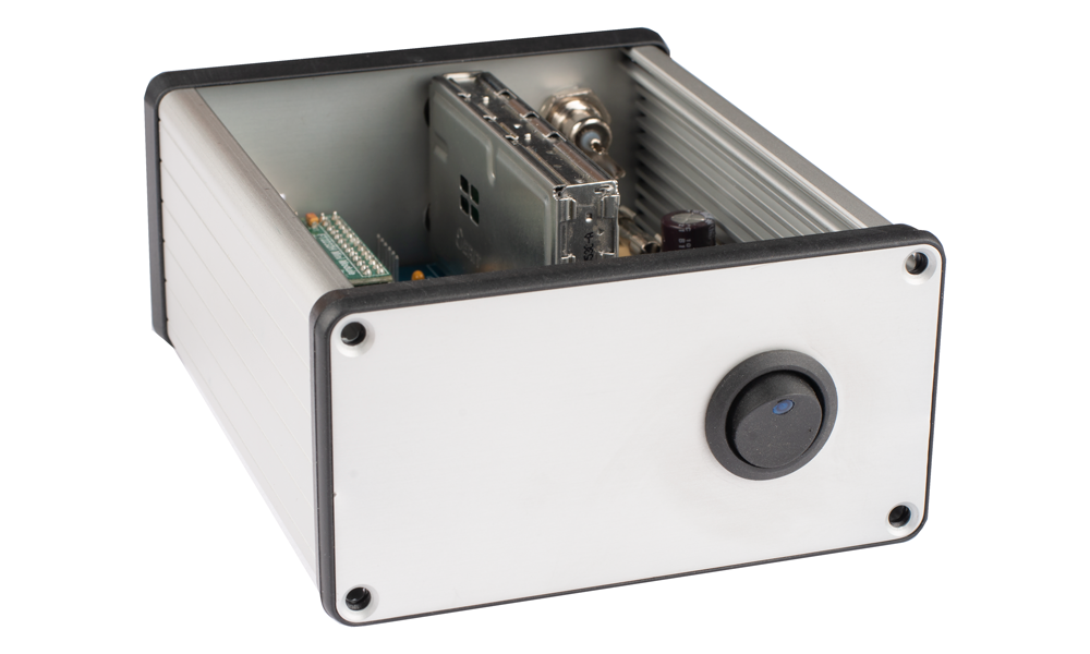
Here is the wiring from the DC socket to the power switch.
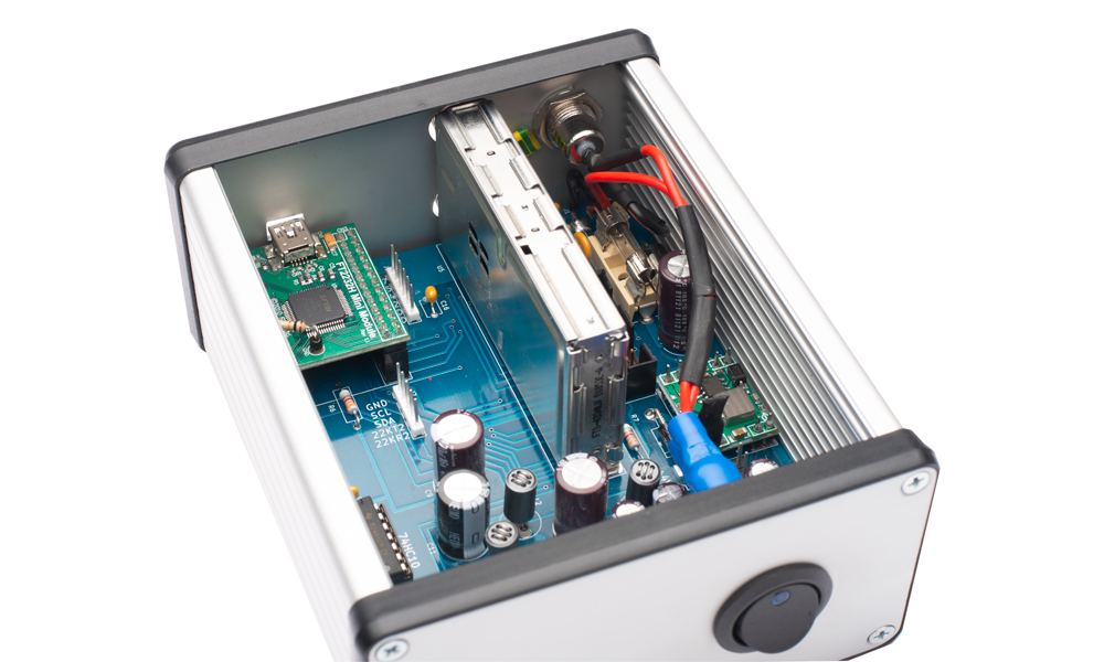
Another photo showing wiring but this time showing how I used crimp connectors. Because the switch has a built in LED indicator the bottom connector of the switch needs to be connected to earth. I did this by soldering one end of the wire to the switch and an M3 eyelet connector to the other end. I then attached the eyelet to the 1V regulator.
The photo below shows completed build.
INSTALLING THE SOFTWARE
After checking the hardware was good I moved onto the MiniTioune software.
To download the software you must first register here. This is not an immediate process as it requires an admin to authorise your request.
The MiniTioune is not connected to the computer at this stage. All of the installs I did using the admin user.
Once approved I downloaded MiniTioune v0.8 here. Software is downloaded in a zip file.
I unzipped the file and the installed ‘LAVFilters-0.71-installer.exe’.
Then I installed ‘install_usrc_ax_winXP_Win10.exe’.
I connected the MiniTiouner to the computer using USB cable and powered the MiniTioune using a 12V power supply.
To test the MiniTiouner is detected and performing correctly I ran ‘CheckMiniTiouneDriverAndFilters_V0_5a.exe’. All tests passed.
I copied the directly to the programs folder in my C:\ drive and created a desktop shortcut to the MiniTioune program ‘MiniTioune_V0_8s.exe’.
I opened ‘minitioune.ini’ and updated ‘OM_ID=M0NWK’, ‘ForumPassword=<myPassword>’,’Locator=IO93OB’ and ‘Ville=NEWARK’.
I clicked on the MniTioune software shortcut on my desktop and this opened the MiniTioune software.
TESTING
On 9th March I installed some new coax so tested my setup by receiving DATV (Digital Amateur Television) from the GB3VL repeater. GB3VL is 23.9km from my QTH and is located on top of Lincoln Cathedral.
On the morning of the test it was very windy so I had my mast lowered (half it’s normal height). I used my WIMO SHF2344 44 element Yagi and G8FEK LNA (shack end). I configured MiniTioune software to receive frequency 1310MHz, DVB-S @ 4MS & 1/2 FEC. Here are the results:
In the afternoon it went still again and I raised my mast to full height. Notice the difference in the constellations.
Why not take a look at my YouTube channel here or Twitter posts here.
You can also register for my website here.
Thanks
73 de M0NWK
![]()

6 comments
Very nice build mate! Cudooes..
Hi Matt, thank you for your kind comments. 73 Adrian
“the MP1584 DC-DC regulator was faulty”. Mine was too! I found the 8 legged chip wasn’t soldered on three of it’s pins, warmed them up with flux, solder and a small iron tip, it works properly now 🙂
Hi Pete, I’m not sure what the problem was with mine. I bought a few which are on the shelf now should I need them. 73.
Hello
My name is Joe call 9H1GT and i am interested in building this tuner as i like to receive the QO-100 but the problem is that i am not a member of the BATC so i can not buy it and i don,t know if there is other from were to buy it.