
In October 2018 I started using a Comtech 23cm transmitter for my ATV operations. Rather than use the 8-way dip switches to tune the transmitter, I decided to work on a project to develop a rotary LCD tuner using an Arduino Uno as the micro-controller. This article shows how I did it, including the code.
I’ve heard of another type of LCD tuner for the Comtech transmitter and it uses a PIC micro-controller. The reason I decided to use an Arduino is firstly because of its flexibility – I can expand functionality beyond just being an LCD tuner (e.g. keypad, temperature display, transmit & receive switching), and secondly because I can make changes or improvements myself as I have access to the code.
KEY REQUIREMENTS
- Use rotary encoder to increase and decrease frequency in 0.5 MHz steps across frequency range of 1240 – 1370 MHz
- Restrict tuning to frequency range of the Comtech 23cm transmitter – 1240 – 1367 MHz
- Set state (on / off) of 8 channel Solid State Relay module (SSR’s) for selected frequency
- Display the frequency on a Liquid Crystal Display (LCD)
- Print information to Arduino serial monitor when working in the IDE (Integrated Development Environment) for development, testing and diagnostics
MY PARTS LIST
Below is a list of parts required for this project:
- KY-040 rotary encoder
- Ardunino UNO Rev3
- 12v to 5V step-down converter
- USB 2.0 type A to USB 2.0 B adaptor
- 8 channel SSD (Solid State Relay)
- 20 x 4 LCD with I2C
- Bezel for LCD
- Comtech 23cm transmitter
- 8 core alarm wire
- Custom circuit board to piggy back onto Arduino
- Header pins
- Aluminium project box
- Aluminium sheet
- Knob from FT-101Z
- Aluminium plate
- Plastic spacers and bolts
- Heatshrink
- Female crimp connectors
- Solder
- Copper braid
- Push to make switch for resetting the Arduino
- N-type panel to SMA connector
- LED and bezel for transmit indicator
- Switch for transmit
- Red & black 3A wire for power
- DC male plug for transmitter
COMTECH TRANSMITTER DIP SWITCH SETTINGS
I purchased the Comtech transmitter from the Lincoln Repeater Group. The PIC micro-controller contains code developed by Terry G7JFI.
Click here to download a PDF document containing the dip switch settings for my Comtech 23cm transmitter.
COMTECH TRANSMITTER
Below is a photo of my 23cm Comtech ATV transmitter (shielding cover removed) and shows the 8-way dip switch module (blue). ![]()
DESOLDERING THE 8-WAY DIP SWITCH
Before de-soldering I removed the PIC microcontroller to ensure it wasn’t damaged by heat. Using my soldering iron and copper braid I de-soldered the 8-way dip switch, removed it from the PCB and cleaned the PCB with PCB & flux cleaner.
![]()
TRANSMITTER CABLE CONNECTORS
I soldered header pins onto the transmitter PCB so I can easily detach the transmitter from the main assembly if required.
![]()
TRANSMITTER MOUNTING HOLES
Careful not to damage any PCB tracks, I drilled two new holes and increased the size of the existing hole so the transmitter can be mounted on plastic spacers using M3 plastic bolts.
TRANSMITTER TO SSD WIRING
To connect up each of the devices I made up wiring looms using alarm wire and female connector housings with crimp and solder connectors.
This is a photo of the SSD to transmitter cable.
![]()
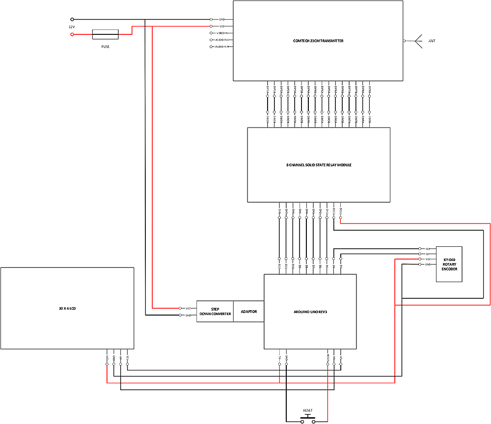
SCHEMATIC
Below is a diagram that shows the schematic for the overall design of my 23cm Comtech LCD tuner.
You can also open a PDF of this document here.
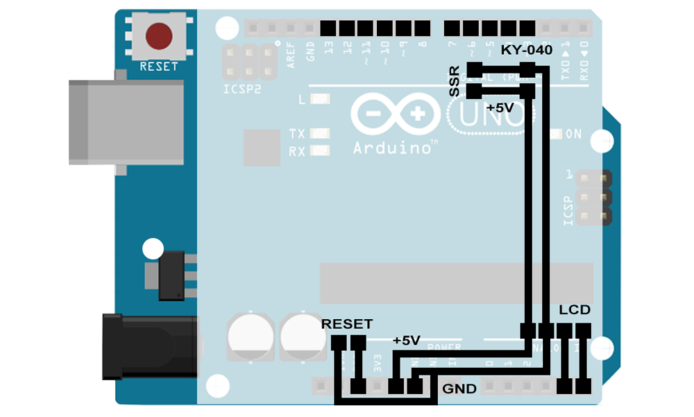
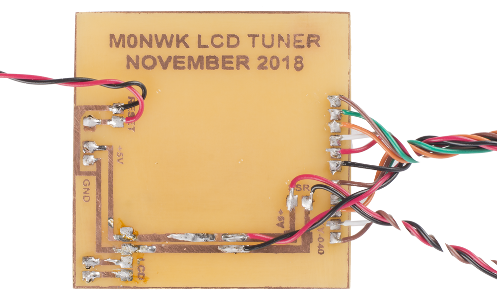
ARDUINO PCB DESIGN
Rather than use jumper wires I designed a PCB to piggy back onto the Ardunino using Photoshop CC. Each module or component is soldered to the PCB.
ETCHING THE PCB
To etch the PCB I used a Press-n-Peel technique. Find out more here.
After all of the wires were soldered to the PCB I used automotive laquer to stop corrosion of the copper tracks on the PCB.
KY-040 ROTARY ENCODER
The Keyes KY-040 rotary encoder is a rotary input device that I will be using to increase and decrease the frequency on the 23cm Comtech transmitter through 0.5MHz steps. See the code section towards the end of this article that shows how I use the rotary encoder position, counters and logic to determine relay state.
Rotation of the KY-040 is continuous in both clockwise and ant-clockwise directions, with a number of fixed positions per revolution. As you rotate the shaft you can feel each of these fixed positions as a light click.
Connection to the Arduino is achieved using four wires (1) + 5V (2) GND (3) DT to a digital pin (4) CLK to a digital pin.
The KY-040 also has a push switch built in (push the shaft). I could have used the centre SW pin to reset the Arduino but opted to install a separate switch on the rear of the panel to avoid pressing it accidentally when rotating the encoder.
![]()
8-CHANNEL SOLID STATE RELAY (SSR) MODULE
I am using an Omron G3MB-202P Solid State Relay (SSR) module. The reason I have opted to use solid state relays is because there are no moving parts. Because of this you don’t hear clicking of relays like you would do with mechanical relays and it can be easily controlled by the Arduino. This SSR is rated 240V 2A.
Each relay is connected to a digital pin on the Arduino. Code I have written determines whether the pin is set to HIGH (1) or LOW (0) depending on the current position of the encoder and calculated frequency. If set to high, the Arduino’s digital pin outputs +5V and this voltage closes the relay switch. This would be the same as switching the dip switch from 0 to 1.
- 0-2.5V – low state – SSR is OFF
- 3.5-5V – high state – SSR is ON
![]()
USB STEP DOWN CONVERTER & USB ADAPTOR
The Arduino can be powered one of two ways; USB connection or external power supply.
– 3 solid state ceramic capacitors (MCC), long life and low ripple
– Synchronous rectification, high efficiency, 6.5V to 5V 0.7A can up to 97.5%, 12V to 5V 1A can up to 94%
– Flat copper inductor
– Output over-voltage protection. 1.5A fuse, 5V output has 300W TVS tube to protect USB device
– Output voltage indicator (RED)
– Size: 26.4 (L) x 15 (W) x 7.4 (H) mm
– Input with reverse polarity protection diode – will not be damaged when input connect incorrectly
– Ultra-low static current – 0.85 mA only. No need to add switch when connected to the car battery
Input voltage: DC 6-24V
Output voltage: 5.1-5.2V
Output current: 3A MAX (please enhance heat dissipation when full load using), the actual test result input 12V output current 2A do not need to enhance heat dissipation.
Conversion efficiency: can up to 97.5% (6.5V step down to 5V 0.7A) (after short reverse protection and fuses test value)
Switch frequency: 500KHz
Output ripple: 10mV around (12V to 5V3A) 20M bandwidth
Output indicator: Output voltage indicator is red
Operating temperature: -40 ℃ to + 85 ℃
Output over-voltage protection: Input t 1.5A fuse, output 5V – 300W TVS tube clamp protection.
Full load temperature: 30 ℃
Static current: 0.85 mA
Load regulation: ± 1%
Voltage Regulation: ± 0.5%
Dynamic response speed: 5% 200uS
Output short circuit protection: Yes
Input reverse polarity protection: Yes
Connection mode: Solder pads
Input mode: Solder pads
Output mode: USB
RESET SWITCH
The push to make switch used for resetting the Arduino connects between the ‘GND’ and ‘RESET’ pins. When the button is pressed it closes the circuit and the Arduino restarts.
WIRING EVERYTHING UP
For my prototype build I connected each of the wires from the transmitter board to the appropriate relay on the Solid State Relay (SSR) module. In the image below you will notice the blue and green wires are soldered to the transmitter PCB. After initially doing this I then decided to use header pins instead so the transmitter can be more easily removed.
I connected each of the relay triggers to a digital pin on the Arduino. The SSR, rotary encoder and LCD receive +VCC and GND from the Arduino. Rotary encoder pins CLK and DT are connected to digital pins on the Arduino. Finally LCD pins SDA and SCL were connected to analogue input pins on the Arduino.
The reset switch is not in this image as I added this later.
![]()
INSTALLING IN CASE
I purchased a really nice aluminium case from eBay.
The photo below shows the cover and both ends removed. Both sides have a rail containing mounting holes.
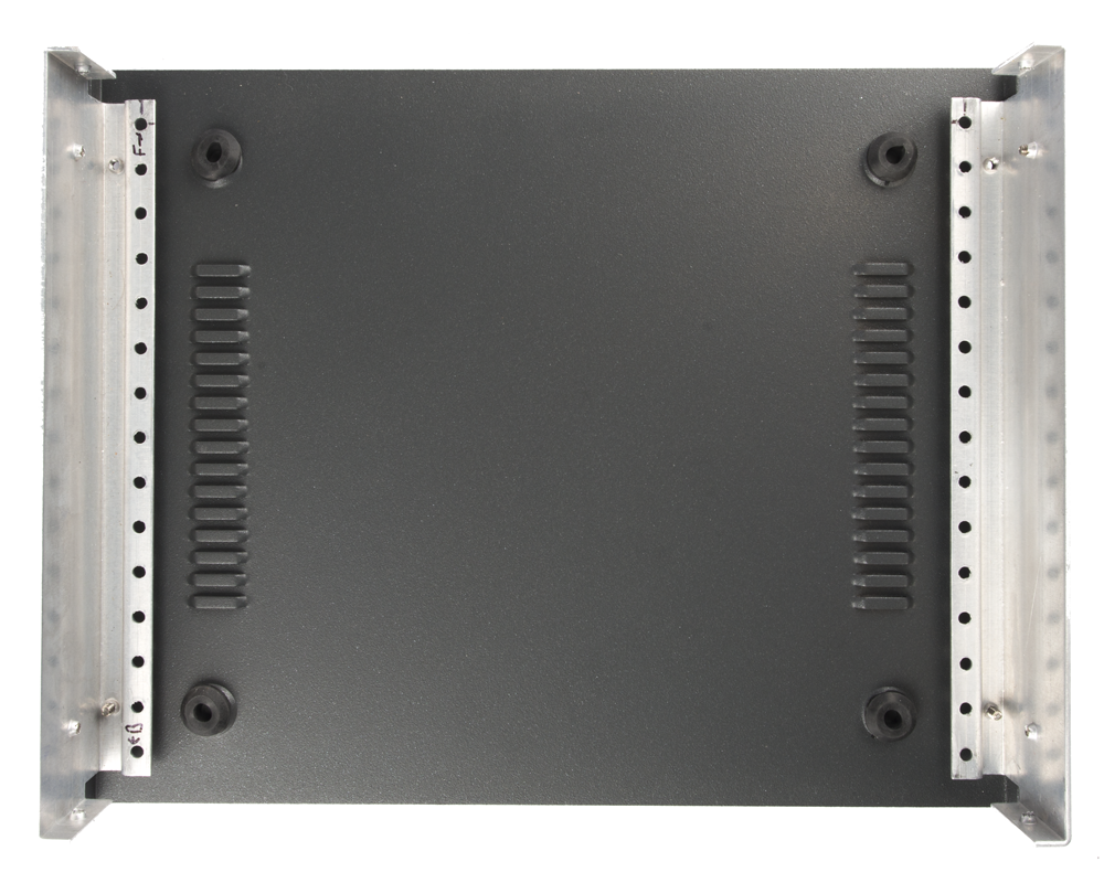
I measured and cut a piece of 3mm aluminium sheet to the dimensions of the base. I then marked the positions of where I wanted each piece of hardware to be mounted and drilled holes.
I finished by spray painting the aluminium with aluminium automotive paint.
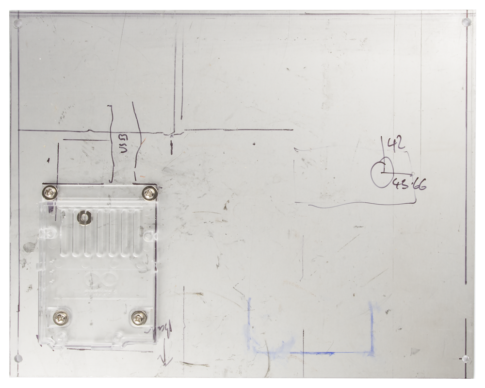
After marking out the window for the LCD on the front panel I started removing material by making a series of holes using a drill before tidying up with a file. I used clamps to hold the LCD in place to drill the four mounting holes.

I drilled all of the holes on the rear panel for the SSD, power socket, N-type connector, fuse holder and phono plugs.
FINISHED PRODUCT
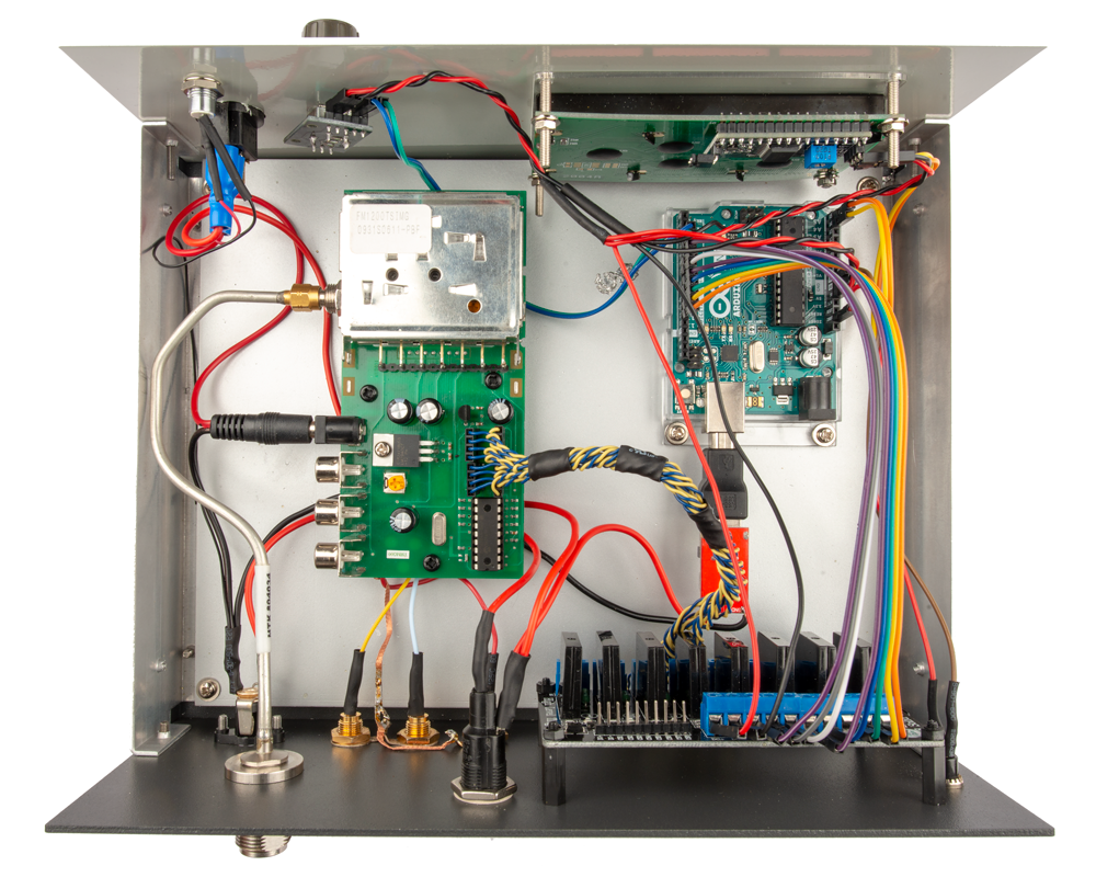
Below are images of my finished 23cm Comtech Amateur Television (ATV) transmitter with LCD tuner.
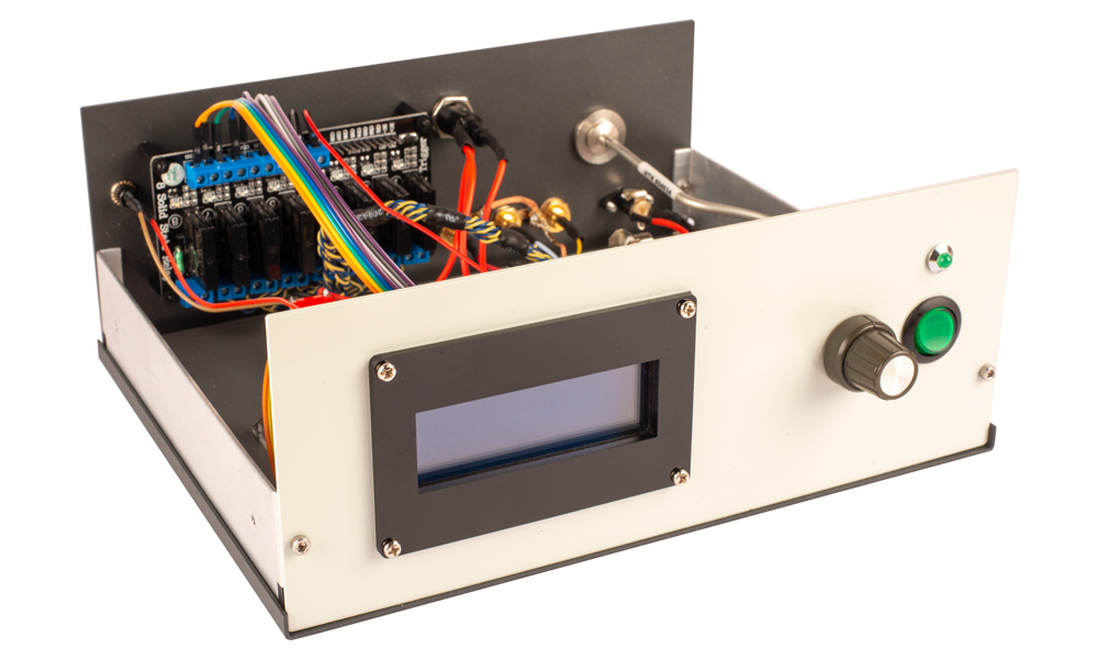
Front panel with 20 x 4 LCD display, tuning knob, transmitter on / off switch and transmit indicator LED.
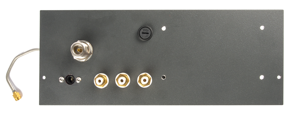
Rear panel showing DC power socket, N-type socket, video and 2 x audio inputs, fuse holder and reset switch.
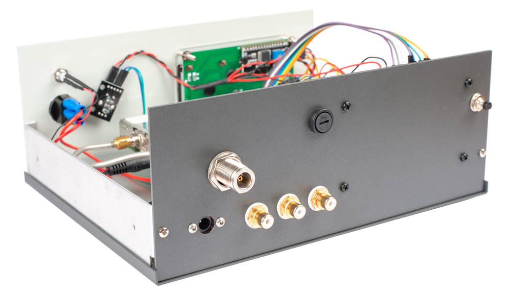
Birds eye view of the component layout. Note that the PCB I etched is not in these images because I decided to develop some new features straight away, which requires a new PCB.
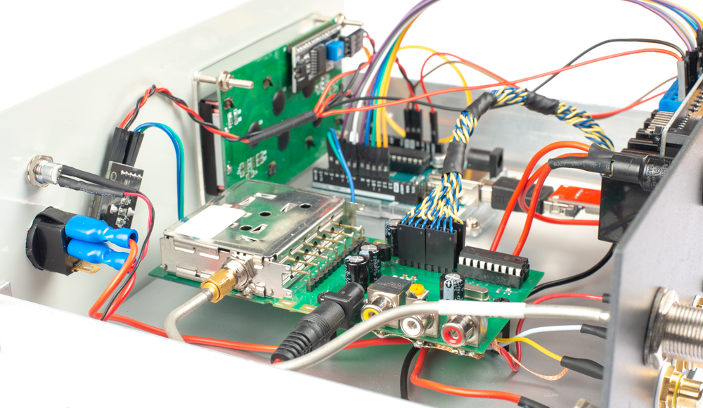
Close up of the Comtech transmitter. I have soldered video and audio cables to the underside of the transmitter PCB allowing me to use the phone inputs for testing.
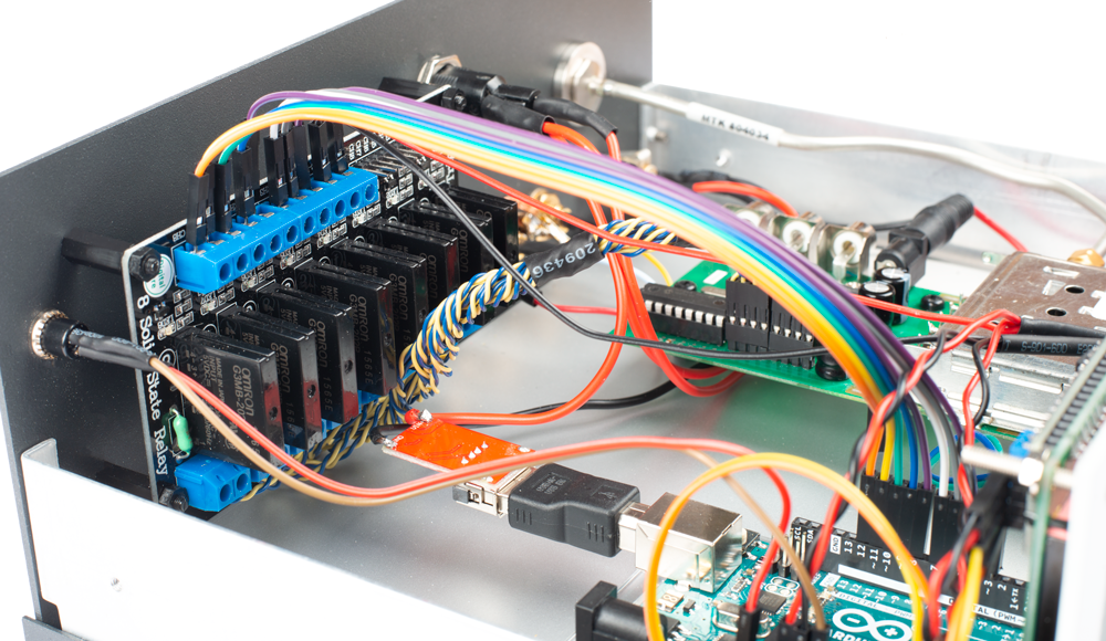
Another close up showing the SSD, reset switch, step down converter and wiring to Arduino.
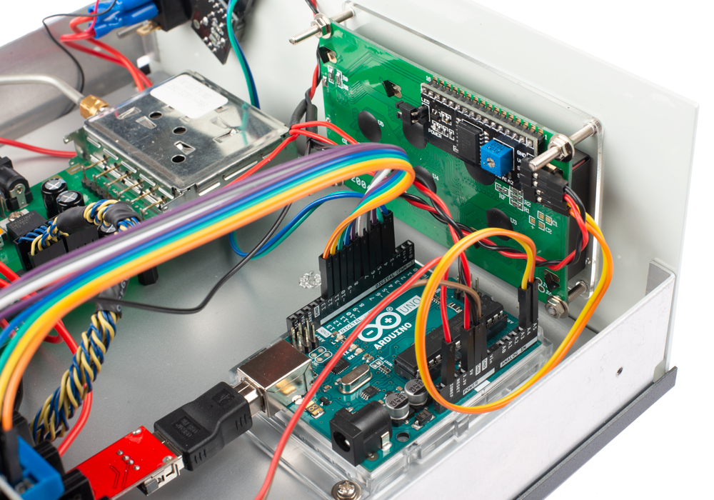
Looking down you can see the rear of the LCD display and connections to the Arduino.
TESTING
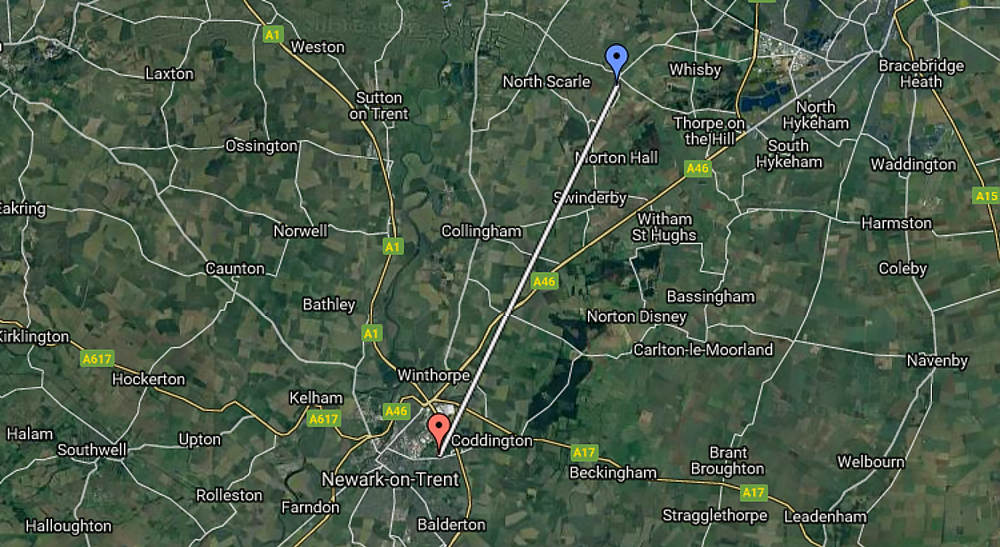
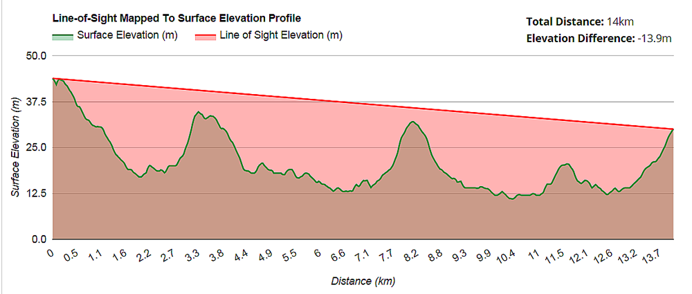
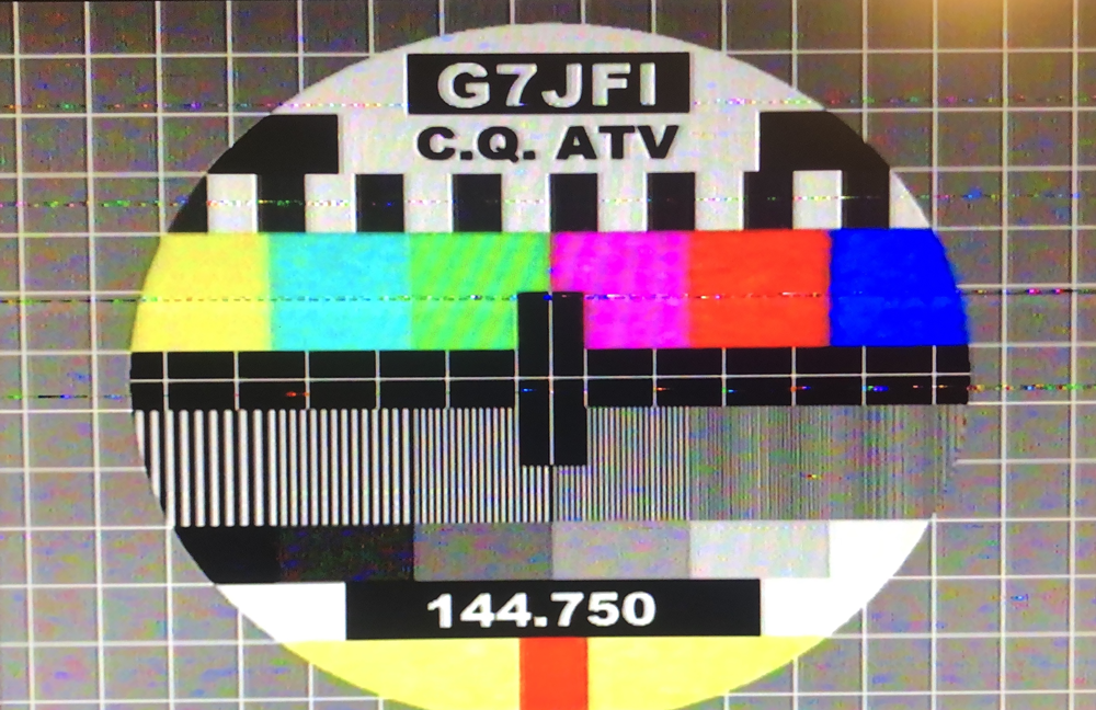
On the evening of 29th November 2018 I tested my Comtech ATV transmitter with Terry, G7JFI – thanks Terry. With only 14km between us as the crow flies, we were delighted to achieve P5 signal both ways.
For transmission I used my homebrew 18W amplifier and WIMO 44 element antenna 45ft from the ground.
Here is an image that Terry took of my test card using his camera.
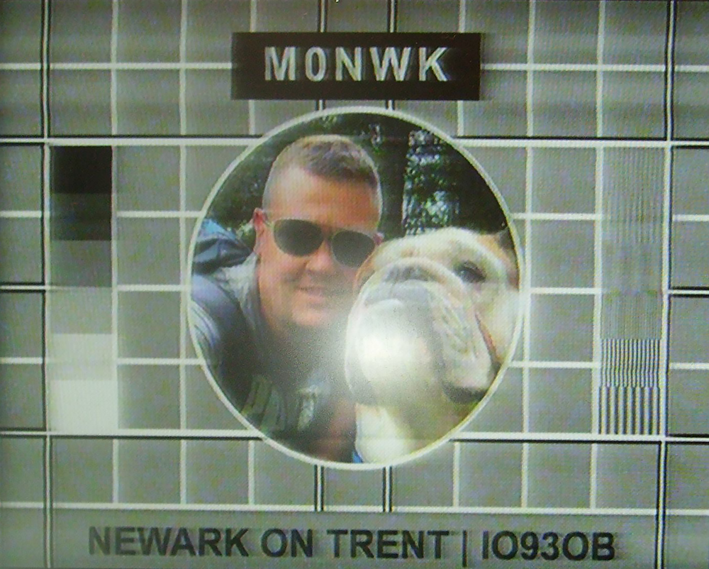
My second test card generated a tone which Terry could hear, albeit faintly. A future modification for my Comtech transmitter will be to add a capacitor in the sub-carrier circuit and add an audio amplifier if needed.
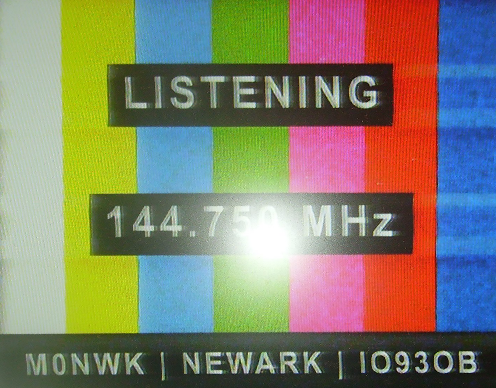
Here are is an image of Terry’s test card taken with my camera. For receive I was using an Analogue Amstrad SRD540 satellite receiver, G8FEK Low Noise Amplifier (LNA) and WIMO 44 element antenna. There was some interference but I believe this was radar.
Another image I took. This time of Terry.

CONCLUSION
The major advantage of this solution is that the transmitter is housed nicely in the case and I can tune it using the rotary encoder rather that the dip switches. I no longer have to lookup the frequency on the chart, record the combinations and change the dip switches and this saves a lot of time. The Arduino solution is expandable so I can add more features quickly and easily. I saw no interference on the transmitted or received signals.
The KY-040 rotary encoder works okay but does miss some steps. This can be forgiven though as it cost only a couple of pounds. In the future I may try an alternative, better quality rotary encoder to see if there is any improvement.
As I mention in the section below, I’m an amateur programmer so although my coding efforts work, I expect there may be some (or lots) of improvements that could enhance the operation of this solution.
ARDUINO CODE
Besides being an amateur radio operator I’m also an amateur programmer and it’s only in the past year or so that I have started to use Arduino in my projects.
Although this code works I’m pretty sure if an experienced programmer looks at it the code can be improved; perhaps significantly – I don’t know.
I will therefore be very grateful for any constructive comments about any improvements that can be made.
CODE – LOGICAL RELAY STATE CALCULATION
This version of code uses sequential counters to determine state of a relay for a given frequency. The current frequency is displayed on the LCD. Information is also sent to the serial monitor for debugging when working in the Arduino IDE.
[code language="csharp"] Comtech 23cm transmitter - rotary encoder & LCD tuner using logic to determine frequency Release version 1.0 - November 2018 / Arduino IDE version 1.17 By Adrian Leggett - amateur radio callsign M0NWK This example code is in the public domain. Using Comtech 23cm transmitter, Arduino UNO, 8 channel Solid State Relay (SSR) module, rotary encoder and 20 x 4 Liquid Crystal Display (LCD) this sketch: - Detects clockwise / anti-clockwise direction of rotary encoder - Calculates relay state based on logic using counters - Sets relay to on / off state according to logic - Displays frequency on LCD The circuit: - Details on website. URL below. Full details of this project here:Comtech 23cm Amateur Television (ATV) rotary LCD tuner using Arduino*/ /*-----( Import libraries )-----*/ #include <LiquidCrystal_I2C.h> // LCD library developed by Francisco Malpartida #include <Wire.h> // Allows you to communicate with I2C device LiquidCrystal_I2C lcd(0x27, 2, 1, 0, 4, 5, 6, 7, 3, POSITIVE); // Set the 20x4 LCD I2C address byte ky_040_clk = 3; // Connected to CLK on KY-040 - date output 1 byte ky_040_dt = 4; // Connected to DT on KY-040 - data output 2 byte encoderPosCount = 0; // 1240MHz - 0 = 1240MHz & 260 = 1367.5MHz byte currentFreqDecVal=0; // Stores the decimal value from the array based on current rotary encoder position value float DisplayFrequency=0000.00; // Stores the calculated frequency based on current rotary encoder position value int ky_040_clkValLast; // Store last value from CLK to determine by comparison the position int ky_040_clkVal; // Store CLK value from KY-040 boolean ky_040_status; // Clockwise = True, Anti-clockwise = False // Variables to store counter values from relay logic calulation byte relay_1_val=0; byte relay_2_val=0; byte relay_3_val=0; byte relay_4_val=0; byte relay_5_val=0; byte relay_6_val=0; byte relay_7_val=0; byte relay_8_val=0; // Variables to store relay states from relay logic calulation byte relay_1_state; byte relay_2_state; byte relay_3_state; byte relay_4_state; byte relay_5_state; byte relay_6_state; byte relay_7_state; byte relay_8_state; void setup(){ // Setup runs once Serial.begin (9600); // Start the serial monitor lcd.begin(20,4); // initialize the lcd for 20 chars 4 lines // Set digital pin type (INPUT / OUTPUT). 5-12 = relays where 5 = relay 1 and 12 = relay 8 pinMode(5, OUTPUT); pinMode(6, OUTPUT); pinMode(7, OUTPUT); pinMode(8, OUTPUT); pinMode(9, OUTPUT); pinMode(10, OUTPUT); pinMode(11, OUTPUT); pinMode(12, OUTPUT); pinMode (ky_040_clk,INPUT);pinMode (ky_040_dt,INPUT); ky_040_clkValLast = digitalRead(ky_040_clk); // Get value of KY-040 CLK. Tells you the last position // Print welcome message to serial monitor Serial.println("Comtech 23cm transmitter - rotary encoder & LCD tuner using logic to determine frequency"); Serial.println(); Serial.println("Release version 1.0 - November 2018 / Arduino IDE version 1.17"); Serial.println(); Serial.println("By Adrian Leggett - amateur radio callsign M0NWK"); // Print welcome messages to LCD lcd.setCursor(2,1); lcd.print("23cm Transmitter"); delay(2000); lcd.clear(); lcd.setCursor(1,1); lcd.print("1240MHz to 1367MHz"); delay(2000); lcd.clear(); lcd.setCursor(4,0); lcd.print("By A Leggett"); lcd.setCursor(3,2); lcd.print("Callsign M0NWK"); delay(2000); lcd.clear(); // Print default frequency and rotary encoder position to serial monitor Serial.println(); Serial.println("***********************"); Serial.println(); Serial.print("Frequency = 1240MHz"); Serial.println(); Serial.print("Default encoder position = "); Serial.println(encoderPosCount); Serial.println(); Serial.print("***********************"); Serial.println(); // Set relays for default 1240MHz (1 = HIGH, 2 = LOW). 1240MHz = 00000000 digitalWrite(5,0); digitalWrite(6,0); digitalWrite(7,0); digitalWrite(8,0); digitalWrite(9,0); digitalWrite(10,0); digitalWrite(11,0); digitalWrite(12,0); // Display default frequency on LCD DisplayFrequency = 1240.00 + (encoderPosCount * 0.5); lcd.setCursor(1,1); // Set cursor position on LCD lcd.print("Frequency: "); lcd.print(DisplayFrequency); // Print msg to LCD lcd.setCursor(1,3); // Set cursor position on LCD } void loop() { ky_040_clkVal = digitalRead(ky_040_clk); // Read value from KY-040 CLK and store in variable if (ky_040_clkVal != ky_040_clkValLast){ // Compare KY-040 current value to last value. If not the same this means rotary encoder is rotating if (digitalRead(ky_040_dt) != ky_040_clkVal) { // Rotary encoder is rotating clockwise if (encoderPosCount <= 253){ // If rotary encoder position is less than or equal to maximum encoder value (highest frequency) then increment encoder position by 1. encoderPosCount ++; // Increment encoder position variable by 1 each iteration // Use counters to determine state of each relay if (relay_1_val == 0){ relay_1_val ++; relay_1_state = 1; }else if (relay_1_val == 1) { relay_1_val --; relay_1_state = 0; } relay_2_val ++; // Relay 2 if (relay_2_val < 2){ relay_2_state = 0; } else if (relay_2_val >= 2 && relay_2_val < 4){ relay_2_state=1; } else if (relay_2_val = 3){ relay_2_state =0; relay_2_val = 0; } relay_3_val ++; // Relay 3 if (relay_3_val < 4){ relay_3_state = 0; } else if (relay_3_val >= 4 && relay_3_val < 8){ relay_3_state=1; } else if (relay_3_val = 7){ relay_3_state =0; relay_3_val = 0; } relay_4_val ++; // Relay 4 if (relay_4_val < 8){ relay_4_state = 0; } else if (relay_4_val >= 8 && relay_4_val < 16){ relay_4_state=1; } else if (relay_4_val = 15){ relay_4_state =0; relay_4_val = 0; } relay_5_val ++; // Relay 5 if (relay_5_val < 16){ relay_5_state = 0; } else if (relay_5_val >= 16 && relay_5_val < 32){ relay_5_state=1; } else if (relay_5_val = 31){ relay_5_state =0; relay_5_val = 0; } relay_6_val ++; // Relay 6 if (relay_6_val < 32){ relay_6_state = 0; } else if (relay_6_val >= 32 && relay_6_val < 64){ relay_6_state=1; } else if (relay_6_val = 63){ relay_6_state =0; relay_6_val = 0; } relay_7_val ++; // Relay 7 if (relay_7_val < 64){ relay_7_state = 0; } else if (relay_7_val >= 64 && relay_7_val < 128){ relay_7_state=1; } else if (relay_7_val = 127){ relay_7_state =0; relay_7_val = 0; relay_8_val ++; // Relay 8 if (relay_8_val < 128){ relay_8_state = 0; } else if (relay_8_val >= 128 && relay_8_val < 256){ relay_8_state=1; } else if (relay_8_val = 255){ relay_8_state =0; relay_8_val = 0; } // Print relay value counters to serial monitor Serial.println(); Serial.println("Relay value counters:"); Serial.print(relay_1_val); Serial.print(relay_2_val); Serial.print(relay_3_val); Serial.print(relay_4_val); Serial.print(relay_5_val); Serial.print(relay_6_val); Serial.print(relay_7_val); Serial.println(relay_8_val); Serial.println(); // Print relay states to serial monitor Serial.println("Relay state values:"); Serial.print(relay_1_state); Serial.print(relay_2_state); Serial.print(relay_3_state); Serial.print(relay_4_state); Serial.print(relay_5_state); Serial.print(relay_6_state); Serial.print(relay_7_state); Serial.println(relay_8_state); } RelayStatus(); // Call function containing common code ky_040_status = true; // Store rotation status as true } else { // Rotary encoder is rotating anti-clockwise ky_040_status = false; // Store rotation status as false if (encoderPosCount > 0){ encoderPosCount --; // Decrement encoder position variable by 1 each iteration // Use counters to determine state of each relay if (relay_1_val == 0){ relay_1_val =1; relay_1_state = 1; } else if (relay_1_val = 1) { relay_1_val=0; relay_1_state = 0; } if (relay_2_val == 0){ relay_2_val=3; relay_2_state = 0; } else if ((relay_2_val > 0) && relay_2_val < 2){ relay_2_val --; relay_2_state = 0; } else if (relay_2_val >= 2 && relay_2_val < 4){ relay_2_val --; relay_2_state=1; } if (relay_3_val == 0){ relay_3_val=7; relay_3_state = 0; } else if ((relay_3_val > 0) && relay_3_val < 4){ relay_3_val --; relay_3_state = 0; } else if (relay_3_val >= 4 && relay_3_val < 8){ relay_3_val --; relay_3_state=1; } if (relay_4_val == 0){ relay_4_val=15; relay_4_state = 0; } else if ((relay_4_val > 0) && relay_4_val < 8){ relay_4_val --; relay_4_state = 0; } else if (relay_4_val >= 8 && relay_4_val < 16){ relay_4_val --; relay_4_state=1; } if (relay_5_val == 0){ relay_5_val=31; relay_5_state = 0; } else if ((relay_5_val > 0) && relay_5_val < 16){ relay_5_val --; relay_5_state = 0; } else if (relay_5_val >= 16 && relay_5_val < 32){ relay_5_val --; relay_5_state=1; } if (relay_6_val == 0){ relay_6_val=63; relay_6_state = 0; } else if ((relay_6_val > 0) && relay_6_val < 32){ relay_6_val --; relay_6_state = 0; } else if (relay_6_val >= 32 && relay_6_val < 64){ relay_6_val --; relay_6_state=1; } if (relay_7_val == 0){ relay_7_val=63; relay_7_state = 0; } else if ((relay_7_val > 0) && relay_7_val < 64){ relay_7_val --; relay_7_state = 0; } else if (relay_7_val >= 64 && relay_7_val < 128){ relay_7_val --; relay_7_state=1; } if (relay_8_val == 0){ relay_8_val=127; relay_8_state = 0; } else if ((relay_8_val > 0) && relay_8_val < 128){ relay_8_val --; relay_8_state = 0; } else if (relay_8_val >= 128 && relay_8_val < 256){ relay_8_val --; relay_8_state=1; } // Print relay value counters to serial monitor Serial.println(); Serial.println("Relay value counters:"); Serial.print(relay_1_val); Serial.print(relay_2_val); Serial.print(relay_3_val); Serial.print(relay_4_val); Serial.print(relay_5_val); Serial.print(relay_6_val); Serial.print(relay_7_val); Serial.println(relay_8_val); Serial.println(); // Print relay states to serial monitor Serial.println("Relay state values:"); Serial.print(relay_1_state); Serial.print(relay_2_state); Serial.print(relay_3_state); Serial.print(relay_4_state); Serial.print(relay_5_state); Serial.print(relay_6_state); Serial.print(relay_7_state); Serial.println(relay_8_state); } RelayStatus(); // Call function containing common code } Serial.println(); } } void RelayStatus() // Common code called by loop for clockwise / anti-clockwise rotation { // Display on LCD current frequency based on current rotary encoder position lcd.clear(); DisplayFrequency = 1240.00 + (encoderPosCount * 0.5); lcd.setCursor(1,1); // Set cursor position on LCD lcd.print("Frequency: "); lcd.print(DisplayFrequency); // Print msg to LCD // Print to serial monitor the current rotary encoder position, frequency and direction of rotation Serial.println(); Serial.println (String("Encoder position: ") + encoderPosCount); Serial.println (String("Frequency: ") + DisplayFrequency); Serial.print (String("Rotated: ")); if (ky_040_status == 1){ Serial.println("Clockwise"); } else if (ky_040_status == 0) { Serial.println("Anti-clockwise"); } // Set state of each relay digitalWrite(5,relay_1_state); digitalWrite(6,relay_2_state); digitalWrite(7,relay_3_state); digitalWrite(8,relay_4_state); digitalWrite(9,relay_5_state); digitalWrite(10,relay_6_state); digitalWrite(11,relay_7_state); digitalWrite(12,relay_8_state); } /code]
Why not take a look at my YouTube channel here or Twitter posts here.
You can also register for my website here.
Thanks
73 de M0NWK


2 comments
hello, about the switching with relays for a SAT tuner
I thing you know that this device works with I2C commands
Arduino can send those commands directly to the tuner
with 3 wires … Data, Clock and ground
OK ??
francois F1CHF
Hi Francois, thank you for your message. Yes I2C will be something I will look at in the future. Uses far fewer pins leaving them spare to be used for other features. Thanks Adrian